IN THE BEGINNING
Most new flyers rely on the club-provided launch rods at the launch site for their initial rocket flights.
Your rocket slips over the rod and is held in a straight trajectory until the rocket has gained sufficient acceleration and airflow over control surfaces (fins) to control the flight path of the rocket. These simple steel rods can, at times, depending on their length and the mass of the launching rocket, sometimes encounter what is known as a "Rod Whip" where under the momentum of launch oscilate the very rod intended to hold the rocket in a predictable flight path.
All rockets flying on either rods or rails require some form of attachment to these. Obviously, any external attachment to the rocket airframe will induce a penalty of drag and affect the rocket's performance.
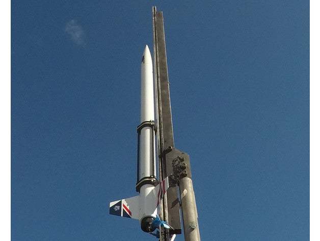
If you are chasing records such as a Mach 1.0 attempt on an AA motor (by the way, that was meant to be a joke) 😀 , then flyaway and similar devices may be of value. Some are available from international vendors, and some are even 3D printable.


3D Printable Version
A new and stronger fly-away rail guide for medium-power and high-power model rocketry. It's used to launch sports rockets as an alternative to gluing on launch lugs or screwing rail buttons directly onto the rocket body.
The guide fits around the rocket with two sets of rail buttons that engage in the launch rail (rails are usually 1010 extruded aluminium). On launch, the guide provides stability as the rocket travels up the rail. As soon as the rocket clears the launch rail, the flyaway guide springs open and detaches from the rocket body to reduce drag in flight.
If you are a 3D printer, you may wish to try out one of the many print designs such as this one.

https://www.thingiverse.com/thing:3706482
Fly-away or Throw-away
These commercial items cost approximately $25 AUD plus shipping and can be prone to loss and breakage after your rocket leaves the launch site. All of which could start to ramp up your cost per launch.
If you're going to make your own from MDF and your CNC, you will also need to ensure that it does not bind to the launch rail, slowing your initial acceleration away from the pad and flirting with potential catastrophy.
Enter the Lugless Launch Tower.
So why not forego Launch Luggs altogether and launch from a tower without such impediments to flight.
A lugless launcher for model rockets represents a method of launching these rockets without using the traditional launch lug. A launch lug is a small tube or guide attached to the side of a model rocket, which slides over a metal rod to guide the rocket during the initial phase of the launch until it achieves sufficient velocity for the fins to stabilize its flight. The lugless launcher, in contrast, uses alternative methods to guide the rocket during takeoff, aiming to reduce drag and possibly improve the aesthetics of the rocket by eliminating the need for the lug.
There are several approaches to designing a lugless launcher. One common method involves using a rail or a slot that the rocket attaches to, allowing for a smooth guide without the protrusion of a lug. This rail or guide system can provide a more stable acceleration phase and is especially beneficial for larger or heavier rockets that require more guidance than a simple rod can provide.
Efficiency in the context of lugless launchers refers to the reduction in aerodynamic drag and the potential for improved launch stability. By eliminating the launch lug, the rocket has a smoother surface, which can slightly reduce drag. This reduction in drag can translate to higher altitudes achieved under the same power conditions, making the system more efficient in performance. Rail or slot-based systems can also offer a more robust guide for the rocket, potentially improving launch stability and predictability, especially in windy conditions or for rockets with higher-power engines.
However, the efficiency gains from using a lugless launcher can vary and might be more noticeable in specific conditions or rocket designs. For hobbyists and professionals alike, the choice between a traditional launch lug system and a lugless system may come down to personal preference, the specific requirements of the rocket being launched, and the conditions expected at the launch site.

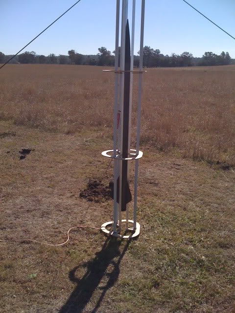
A Lugless Tower at Cedar Grove - Winter 2011

38mm Minimum Diameter Carbon Fibre Mach Attempt - Although the tower was well-stayed and pegged with guy lines, a heavier base and some form of blast deflection may have been advantageous.

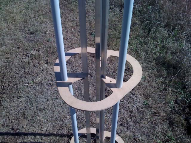
The base frame comprised 3 Aluminium right-angle extrusions that fitted snugly against the airframe. As shown above, these were held in place by 4 x MDF plates. 3 x 3 Meter threaded rod sections allowed for plate adjustment, and PVC conduit protected these segments
Please let me know your thoughts ...
Thanks for the article Len. That's my "Flight of the Concordes" PML Callisto with the Additive Aerospace 54mm fly-away rail guide on it. The fins were hand painted with three different British Airways tailfin logos that Concorde flew with. Sadly, the only thing I have left is the fly-away guide which I always have in by range box if anyone needs to borrow one!
It was last seen at Cedar Grove in Jan 2020 flying to 3000ft on an Aerotech DMS I140, but the chute probably opened at apogee and it wasn't seen again. Lost the Callisto, the Jolly Logic Chute Release and the Jolly Logic Altimeter 3 in it. 😞 😞
The limited flights using the fly-away guide, my impression was that there were not any real altitude benefits from using it. My theory is that the guide has to be accelerated with the rocket off the launch rail, therefore it steals some of the energy of the motor to accelerate its mass too, and this effect may be more disproportionate in very short burn motors. The 54mm guide I was using weights 140gms. Perhaps the benefits would be better if they were paired with long burn motors which would still be accelerating the "aerodynamically clean" rocket well after the rail guide has separated.
Anyhow, I've now tended towards low profile and contoured rail guides, such as the two products in the attached photo.
AMRS Level 1 - PML Callisto May19 H100W 3600ft
AMRS/Tripoli Level 2 - 3" AGM33 Pike Aug20 J270W 3300ft
First Airstart - Thales Starstreak Mar22
First Cluster - Banana Republican Jun23 3xE20 1856ft
Impulse tally - 11,019NS since May 2019
To chime in - yeah I'm with Brendan.
We experimented with fly-away guides a couple years back and it was always a tricky balance to get the fly-away guide to stay in place and support the airframe without putting extra friction and drag as the rocket travels up the rail, then to release very quickly when it gets to the end of the rail and the rocket is still boosting in free flight.
Ultimately this design for fly-away guides was shelved as it couldn't snap open quickly enough no matter how hard we tried - I had a bunch of 'fin strikes' on smaller rockets where the rail guide was hit by the rocket fin on its way past, which occasionally shattered the hinges
Lugless Launch Towers are the way to go IMHO 🙂
Hi Guys
I wonder if QRS were to obtain a "luggless" tower as shown above, what diameter airframe do you think we would need to accommodate it?
(I feel I may become just a little anxious if anyone comes back with 98 or 150mm.) 😀
The beauty of the design, as shown above, is that if you need to change from 30mm to 50mm, all you need to replace during the launch is the three mdf segment and stake it all down again. With a little bit of further modification, you could overlay and bolt in a 30mm guide on top of a 50mm one and just reattach the aluminium launch rails.

Does anyone have a suggested better design?
The launch tower pictured belonged to a former QRS member known as "Pink Hat".
Does anyone know if he is still about?
I recall he went with the Queensland contingent to WA in 2011, but I never saw him after that. (perhaps it was something in the water)
Len Forsyth
On the size debate, I would venture there would be higher demand for 38mm and 54mm, with occasional demand for 75mm.
I've been tempted to start building a tower before and after thought, I'd decided that the build would either need to be easily adjustable in the field for these 3 sizes, or it would be so easy and not cost prohibitive to make that we could simply make one of each size without the need to adjust but simply interchange each tower onto a base, like a Rockwell JawStand. However, for tall rockets (very tall towers), the stability of the jawstand would be tricky and need some practice.
Attached is a design "mood-board" of ideas I liked when trolling through the US Rocketry Forum of build projects and ideas I liked.
AMRS Level 1 - PML Callisto May19 H100W 3600ft
AMRS/Tripoli Level 2 - 3" AGM33 Pike Aug20 J270W 3300ft
First Airstart - Thales Starstreak Mar22
First Cluster - Banana Republican Jun23 3xE20 1856ft
Impulse tally - 11,019NS since May 2019
Time for my 2c!
There is a tower in the trailer, or there was anyway. It's in a few pieces that need to be put together and I don't believe there are any straps for it. It was adjustable to be able to accommodate varying air frame sizes. I've got a photo of it somewhere with my Blackhawk 38 loaded up. Structurally it looked like the first tower in Brendan's PowerPoint slides only a lot more beat up.
Not sure who built those towers, the picture of one sitting on the ground with the straps holding the tower stable looks very, very similar to one that Warren built for his altitude record attempts.
I like the look of the airfoil rail guides, there's not going to be much difference compared to the normal rail buttons: they will just stabilize the air flow below the button.
QRS President
Tripoli #13468 L3
Tripoli Prefect #131
Tripoli TAP Member
Hi Matt,
I'd heard there was a QRS Club tower somewhere. I've never seen it in person, only Warren's one. If we can get hold of all the bits at the next launch day, then maybe I can have a look at it and see if I can repair/refurbish it for general use again.
On the Airfoiled 1010 rail buttons, the Apogee site references research that states that these have a 47% reduced drag over a standard circular 1010 button, and if you round off the upper edge, even up to 58% less drag. I've installed these onto the my 54mm fibreglass "Fright of the Concordes" rocket, plus I have a few spare sets of them in 1010 size in my build spares if you want to check them out.
AMRS Level 1 - PML Callisto May19 H100W 3600ft
AMRS/Tripoli Level 2 - 3" AGM33 Pike Aug20 J270W 3300ft
First Airstart - Thales Starstreak Mar22
First Cluster - Banana Republican Jun23 3xE20 1856ft
Impulse tally - 11,019NS since May 2019
That surprises me... Looks like I've got a 26MB / 34 page research report to read...
The launch tower is in a bunch of pieces: a stand that plugs into a circular base then each of the arms of the tower slot into the base. I'm not sure where any of my pre-2020 photos are, if I find them I'll post a pic here...
QRS President
Tripoli #13468 L3
Tripoli Prefect #131
Tripoli TAP Member
Hi Matt,
I’ve skim read the report. Don't bother yourself unless it feeds your inner nerd! The summary and conclusions pretty much nail it, and I could further summarize it with a “No shit, Sherlock” jibe.
Back in my Aerodynamics days at university, I’d performed low-speed wind tunnel testing on wing root fillet designs vs no wing root fillets for subsonic low-set mono-plane wings, and the results were very similar to the CFD observations reported here by the author. The tear-drop shape of airplane drop tanks, wing root shapes on the best WW2 fighters, and the shapes of early land speed record racers were that certain shape for a reason!
Back in my uni days in the mid-80s, CFD was a whole new dark arts world without the backing of any computers. It was the time of the early transition towards real head twister mathematical CFD vs practical real word testing, only hampered by the lack of computing power of the day. The most powerful desktop computer our university’s Engineering department had was a single ZX Spectrum and a BBC computer, both with about 32k of RAM. The internet was but a wet dream.
I loved the image of the Porsche 911 in his report. It reminded me of another “test” my mate and I performed at uni. We bought a Matchbox VW Beetle toy car, metal body of course, super glued its wheels to a metal plate, and then we put it in the transonic wind-tunnel and flew it! Somewhere, out there, there is a shadow-graph photo of a VW Beetle going supersonic with beautiful shockwave patterns across it’s body!
AMRS Level 1 - PML Callisto May19 H100W 3600ft
AMRS/Tripoli Level 2 - 3" AGM33 Pike Aug20 J270W 3300ft
First Airstart - Thales Starstreak Mar22
First Cluster - Banana Republican Jun23 3xE20 1856ft
Impulse tally - 11,019NS since May 2019
I’ve skim read the report. Don't bother yourself
Good news! And you agree with their findings?
I thought I was doing it tough in undergrad having to use Apple ][ computers... I would like to add a ZX Spectrum 48k and BBC to my collection though...
QRS President
Tripoli #13468 L3
Tripoli Prefect #131
Tripoli TAP Member
QRS President
Tripoli #13468 L3
Tripoli Prefect #131
Tripoli TAP Member
